Dissipative structural behaviour
Earthquake-resistant timber buildings should be designed considering either:
- dissipative structural behaviour;
- low-dissipative structural behaviour.
In the first concept the capability of parts of the structure (dissipative zones) to resist earthquake actions out of their elastic range is taken into account. Dissipative zones shall be located in joints and connections, whereas the timber members themselves shall be regarded as behaving elastically.
In the second concept the action effects are calculated on the basis of an elastic global analysis without taking into account non-linear material behaviour.
Ductility classes and overstrength factor
Depending on their ductile behaviour and energy dissipation capacity under seismic actions, buildings shall be assigned to one of the three following ductility classes:
- DCH, high capacity to dissipate energy;
- DCM, medium capacity to dissipate energy;
- DCL, low capacity to dissipate energy.
In DCH and DCM the European standard (UNI EN 1998-1 §8.1.3) requires the use of the capacity design procedure.
The capacity design has the purpose of ensuring a ductile behaviour to the dissipative structure and operates as follows:
- distinguishes elements and mechanisms, both local and global, into ductile and fragile;
- aims to avoid local brittle ruptures and the activation of global brittle or unstable mechanisms;
- aims at locating the energy dissipations by hysteresis in areas of the ductile elements identified and designed for this purpose.
To ensure the correct behaviour of the structure, the seismic resistance of the local/global brittle elements/mechanisms must be designed to be grater than that of the ductile elements/mechanisms. To ensure compliance with this inequality, both locally and globally, the strength of the ductile elements/mechanisms is increased by means of a suitable coefficient γRd known as the “overstrength factor”; starting from this increased capacity, the capacity of the brittle elements/mechanisms is sized. This coefficient is defined as equal to 1.3 for the ductility class DCM and 1.6 for the ductility class DCH.
The resistance demand evaluated with the capacity design criteria can be assumed not to exceed the strength demand evaluated for the non-dissipative structural behaviour.
Calculation procedure
Applying capacity design locally and globally
The capacity design imposes, as a preliminary step, the definition of which are the dissipative zones and which are the non-dissipative zones. These zones depend on the ductility class adopted and on the structural typology
Planning according to capacity design procedures is therefore divided into two application “levels”:
- local level, related to the connection of the structure;
- global level, related to the walls and the building.
The first has the purpose of avoiding the prevalence of brittle failure modes in dissipative connections. The second instead provides for the application of a series of rules aimed at avoiding non-dissipative collapse mechanisms and fragile breakages of the elements that make up the structure.
Calculation of design resistances
The design strength of the dissipative zones is defined by the following formula:
$$F_{Rd,ductile} = k_{R,deg} \cdot k_{mod} \cdot \frac{F_{Rk,ductile}}{\gamma_M}$$
where:
FRd,ductile is the design value of the strength of the dissipative zones;
kR,deg is the strength reduction factor due to cyclic degradation;
kmod is the modification factor for duration of load and moisture content;
FRk,ductile is the characteristic value of the strength of the dissipative zones;
γM is the material partial factor.
The design strength of the non-dissipative zones is defined by the following formula:
$$F_{Rd,brittle} = k_{mod} \cdot \frac{F_{Rk,brittle}}{\gamma_M}$$
where:
FRd,brittle is the design value of the strength of the non-dissipative zones;
kmod is the modification factor for duration of load and moisture content;
FRk,brittle is the characteristic value of the strength of the non-dissipative zones;
γM is the material partial factor.
Check dissipative zones
The dissipative zones against the seismic actions calculated with the dissipative behavior factor need to be verified according to the following expression:
$$F_{Ed,ductile} \leq F_{Rd,ductile} = k_{R,deg} \cdot k_{mod} \cdot \frac{F_{Rk,ductile}}{\gamma_M}$$
Check non-dissipative zones – Local level
In order to ensure compliance with the rules of capacity design at the local level (connection), it must be verified that the resistances associated with the brittle failure modes are over-resistant compared to the resistance associated with the ductile failure mode:
$$F_{Rd,brittle} \geq \frac{\gamma_{Rd}}{k_{R,deg}} \cdot F_{Rd,ductile}$$
where:
γRd is the overstrength factor;
kR,deg is the resistance degradation coefficient due to cyclic actions;
FRd,ductile is the design value of the strength of the dissipative zones;
FRd,brittle is the design value of the strength of the non-dissipative zones.
In other words, the fragile elements of the dissipative connections must be verified for a stress equal to:
$$F_{Ed,brittle} = \frac{\gamma_{Rd}}{k_{R,deg}} \cdot F_{Rd,ductile}$$
Check non-dissipative zones – Global level
The non-dissipative zones need to be checked towards the actions deriving from the application of the capacity design rules. The design effect of the actions is obtained through the following relationship:
$$F_{Ed,brittle} = \Omega \cdot F_{Ed,brittle,E} + F_{Ed,brittle,G}$$
where:
Ω is the structure overstrength ratio (in both x and y directions);
FEd,brittle,E is the action effect in the non-dissipative connection or member of the design seismic action;
FEd,brittle,G is the action effect in the non-dissipative connection or member of the non-seismic actions in the design seismic situation.
Dissipative zones and non-dissipative zones
CLT in ductility class DCM
For a CLT building in ductility class DCM, the dissipative zones consist of:
- mechanical connections between walls;
- ductile elements of the tension connection (for example the nailing);
- ductile elements of the shear connection (for example the nailing).
The non-dissipative zones are instead represented by:
- brittle elements of the tension connection (for example the concrete anchors);
- brittle elements of the shear connection (for example the concrete anchors);
- timber elements.
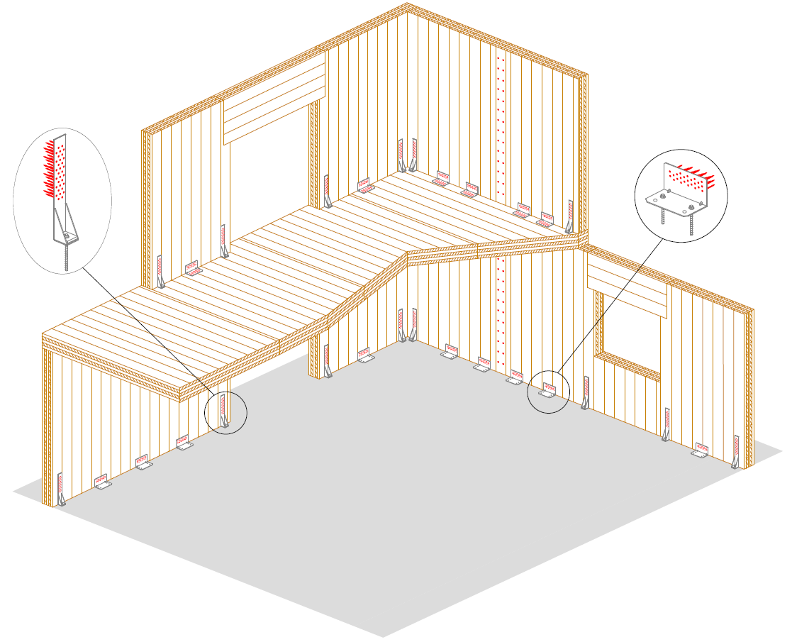
CLT building in ductility class DCM: dissipative zones
Light timber frame in ductility class DCM
For a light timber frame building, the dissipative zones consist of:
- mechanical connection between frame and cladding sheets;
- ductile elements of the tension connection (for example the nailing);
- ductile elements of the shear connection (for example the nailing).
The non-dissipative zones are instead represented by:
- cladding sheets;
- brittle elements of the tension connection (for example the concrete anchors);
- brittle elements of the shear connection (for example the concrete anchors);
- timber elements.
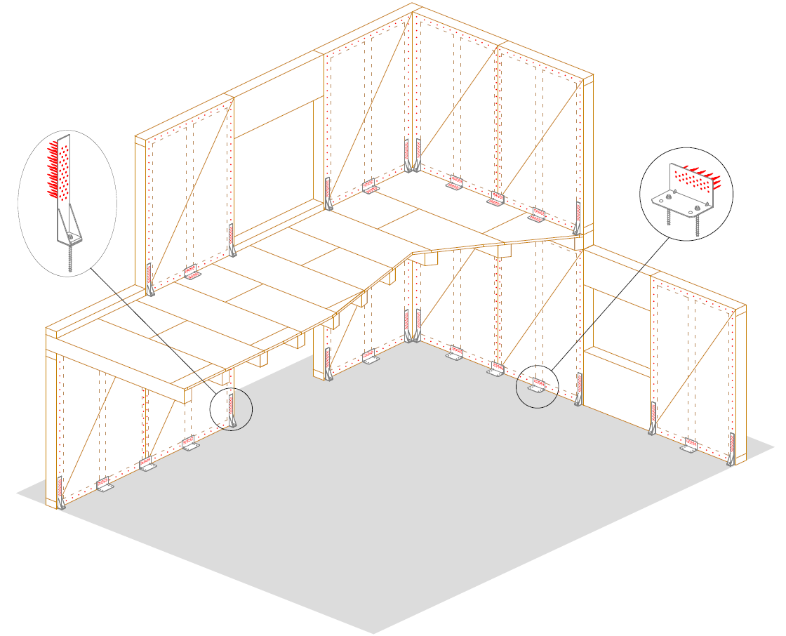
Light timber frame building in ductility class DCM: dissipative zones
Light timber frame in ductility class DCH
For a light timber frame building, the dissipative zones consist of:
- mechanical connection between frame and cladding sheets.
The non-dissipative zones are instead represented by:
- cladding sheets;
- tension connection;
- shear connection;
- timber elements.
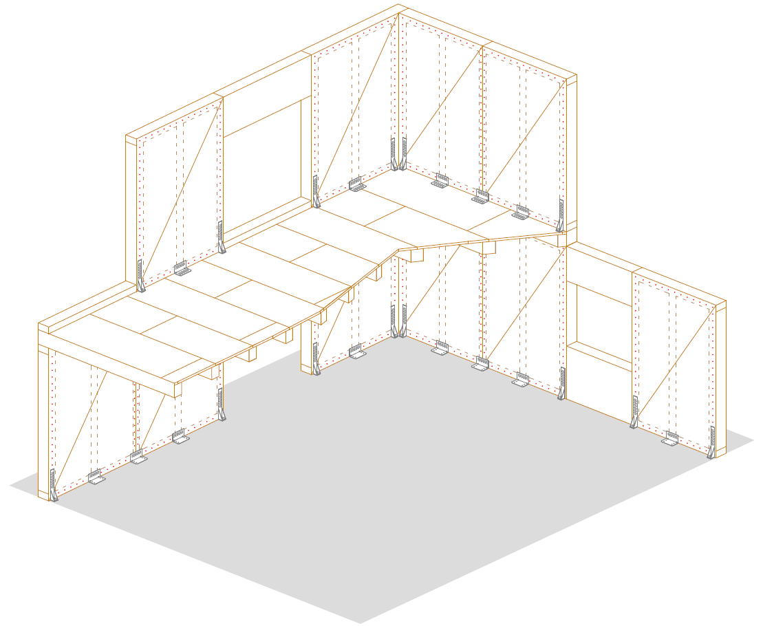
Light timber frame building in ductility class DCH: dissipative zones
Other videos on our YouTube Channel